

Views: 0 Author: Site Editor Publish Time: 2026-09-01 Origin: Site


Over-the-air (OTA) broadcast television provides free access to high-definition TV signals without requiring monthly subscriptions, but achieving stable reception is rarely as simple as plug-and-play. From the distance between your antenna and broadcast towers to high-frequency signal attenuation, coaxial cable loss, and potential interference from nearby wireless systems, every part of the signal path affects reception quality.
Improving OTA reception does not always require expensive equipment upgrades. By understanding how antenna placement, signal strength, cable selection, and interference control work together, you can reduce pixelation, recover lost channels, and build a more reliable TV antenna system.
Poor TV antenna reception is usually the result of signal loss somewhere between the broadcast transmitter and the TV tuner. Antenna gain, frequency coverage, transmission distance, physical obstructions, multipath interference, and cable loss can all reduce the signal margin available for reliable reception.
Antenna gain directly affects the signal level available at the receiver. In weak-signal areas, insufficient gain can leave the received signal too close to the tuner’s decoding threshold, resulting in missing channels, pixelation, or frozen images.
For reference, FCC DTV planning calculations use a nominal receiver input level of about −84 dBm for UHF reception. Once the signal approaches this threshold, even a relatively small additional loss can affect reception stability.
TV broadcasts operate across different VHF and UHF frequency ranges, so an antenna must provide suitable performance across the frequencies used by the target channels. If a channel falls outside or near the edge of an antenna's effective range, its received signal can be significantly weaker than channels within the antenna's optimal range.
This is why an antenna can receive some channels clearly while struggling with others, even when those channels are transmitted from the same general area.
Signal strength decreases as the distance between the transmitter and receiving antenna increases. Hills, mountains, buildings, and other large structures can further attenuate the direct signal by blocking the line-of-sight path.
A small reduction in signal level can matter when the system has little reception margin. Digital TV also has a relatively sharp transition around the decoding threshold: ATSC describes a "cliff effect," where a small signal degradation can cause reception to change rapidly from a clean picture to frozen or blank video.
TV signals can reflect from buildings, metal structures, vehicles, and other objects before reaching the antenna. The direct and reflected signals may then arrive with different phases and interfere with each other.
ATSC receiver guidelines specifically consider multipath handling as an important part of reliable digital TV reception. This effect is particularly relevant in dense urban environments, where multiple reflection paths can exist around the antenna.
Even when the antenna receives an adequate signal, part of that signal is lost before it reaches the TV. Cable attenuation increases with cable length and generally becomes more significant at higher frequencies.
As a reference point, FCC DTV planning factors assume about 1 dB of downlead loss for 15 m (50 ft) of low-VHF coaxial cable, 2 dB for high VHF, and 4 dB for UHF. Connectors, adapters, and splitters introduce additional losses on top of the cable attenuation.
Choosing a TV antenna should start with the requirements of the installation, not simply the highest gain listed on the datasheet. Before comparing models, identify the required frequency band, signal direction, expected signal conditions, and mounting environment. These factors determine which antenna specifications actually matter for the application.
First, check the frequencies of the TV channels you need to receive. Then compare them with the antenna's specified frequency range. If you need to receive channels from 500 MHz to 680 MHz, for example, choose an antenna whose effective operating range covers the entire 500–680 MHz range rather than only part of it.
If the main TV transmitter is known and the installation has a clear target direction, a directional antenna is usually the better choice. Its radiation pattern concentrates reception toward the transmitter and can provide higher gain in the desired direction.
If broadcasts need to be received from substantially different directions, an omnidirectional antenna may be more practical. This is particularly useful when the antenna cannot be manually repositioned or when the installation is designed to receive signals from multiple transmitters.
As a practical reference, 5–8 dBi is suitable for installations within about 20 km (12 mi) of the transmitter with relatively few obstructions, while 8–12 dBi is a better starting point for distances of around 20–50 km (12–31 mi) or moderate obstructions. For installations more than 50 km (31 mi) from the transmitter or in areas with significant terrain or building obstructions, consider 12 dBi or higher to provide additional signal margin.
For professional installations, several specifications should be checked together rather than evaluating the antenna by gain alone.
· Impedance: TV antenna systems commonly use 75 Ω, so the antenna should match the impedance of the connected RF equipment and cable system.
· VSWR: A specification of ≤2.0:1 across the operating band is a practical benchmark; a lower value such as ≤1.5:1 indicates better impedance matching.
· Polarization: Match the antenna polarization to the transmitted signal whenever the broadcast system specifies one. A polarization mismatch can reduce the received signal level.
· Front-to-back ratio: For directional antennas, a higher front-to-back ratio can help reject signals arriving from behind the antenna, which is useful in environments with unwanted reflected or competing signals.
Outdoor installations require matching specs to the environment. Choose an IP65 or IP66 rating with a −40°C to +70°C operating range, housed in UV-resistant and corrosion-proof materials.For rooftop or mast installations, verify wind-load ratings at the actual height and use mast-mounting hardware, whereas vehicle deployments require vibration-resistant hardware.
Need High-Performance TV Antennas for Your Project?
AsiaLeren supplies industrial-grade directional and omnidirectional TV antennas engineered with up to 12+ dBi gain, VSWR ≤ 1.5, and IP66 weatherproof housings built for harsh outdoor environments.
➔Explore Custom TV Antenna Solutions for Your Environment
What to Check | Choose This |
Broadcast band | VHF → VHF antenna; UHF → UHF antenna; VHF + UHF → VHF/UHF antenna |
Distance from transmitter | ≤20 km → 5–8 dBi; 20–50 km → 8–12 dBi; >50 km → 12+ dBi |
Signal direction | One known direction → Directional; Multiple directions → Omnidirectional |
Outdoor installation | Normal exposure → IP65; Heavy rain/direct exposure → IP66 |
Long-term outdoor use | UV-resistant radome + corrosion-resistant hardware |
Even a properly selected TV antenna can underperform if it is installed in the wrong position. For stronger and more stable reception, focus on installation height, antenna orientation, and the actual clearance around the antenna.
For outdoor reception, mount the antenna above nearby roofs, trees, and other major obstructions whenever possible. As a reference, FCC DTV planning calculations use an outdoor receiving antenna height of about 9 m (30 ft) above ground. This is not a universal requirement, but it provides a useful benchmark for fixed installations.
More importantly, choose the position with the clearest path toward the transmitter rather than simply choosing the highest point. A slightly lower location with fewer obstructions can perform better than a higher position blocked by nearby structures.
For a directional antenna, first point the antenna toward the main transmitter, then make small azimuth adjustments while checking the received signal. Do not stop at the first position where channels appear; the best position is the one that provides the highest and most stable signal quality across the required channels.
This is particularly important in multipath-prone locations. ATSC testing notes that antenna characteristics and orientation affect the amount of multipath received, so a small change in position or direction can sometimes improve reception without changing the antenna itself.
Avoid placing the antenna directly beside large metal structures, walls, or other objects that can reflect or block RF signals. When reception is unstable, test more than one mounting position rather than assuming that height alone will solve the problem.
After finding the best location and direction, secure the antenna firmly so wind or vibration cannot change its alignment. This matters especially for directional antennas with narrow beamwidths.
A practical installation sequence is: raise the antenna above major obstructions, aim it toward the transmitter, check signal quality while fine-tuning the position, and then lock the antenna firmly in place.
Coaxial cable gradually introduces signal loss between the antenna and TV receiver, especially when the cable run is long, the frequency is high, or multiple connection points are used. Therefore, minimizing unnecessary cable loss is important for maintaining stable OTA TV reception.
· Prefer RG6 Coaxial Cable: Most residential OTA TV systems use 75Ω RG6, which generally provides lower loss and better shielding than RG59. For longer cable runs, RG11 can be considered.
· Keep the Cable Run as Short as Practical: Cable loss increases with both cable length and frequency. For example, if a cable has an attenuation of approximately 6 dB per 100 ft (30 m) at a given frequency, a 50-ft (15 m) run could introduce around 3 dB of loss, even before accounting for connectors and splitters.
· Minimize Connectors and Splitters: Each additional connection can introduce insertion loss and creates another potential point for poor contact or signal degradation.
· Protect Outdoor Connections from Water: Moisture entering outdoor connectors can increase signal attenuation and cause intermittent reception problems, such as channel dropouts or pixelation.
In weak-signal areas, the key is to determine whether the system is limited by low signal level, poor signal quality, or excessive downstream loss. A few practical measurements can help identify the actual problem before replacing the antenna or adding an amplifier.
· Check Signal Level at the Antenna Output: Measure the RF level directly at the antenna output before the signal passes through long coaxial cables or splitters. If the signal is already very low at the antenna, the reception environment is the primary limitation. If the signal is adequate at the antenna but drops significantly at the TV, cable or distribution loss should be investigated.
· Use SNR or MER to Evaluate Digital TV Quality: For digital TV, signal strength alone is not enough. A stronger signal with poor quality may still produce pixelation or dropouts. Where the receiver provides SNR/MER readings, use them together with signal level to distinguish between a weak signal and a noisy or distorted signal.
· Maintain a Reception Margin: Do not design the system to operate exactly at the tuner’s minimum threshold. For example, if a receiver requires around 15 dB SNR for reliable decoding, maintaining several dB of additional margin helps the system tolerate changes caused by weather, cable loss, or interference.
· Check for Frequency-Specific Problems: If only certain VHF or UHF channels are unstable while others remain strong, the problem may be frequency-dependent rather than a general lack of signal. Compare the affected channels and check antenna bandwidth, cable attenuation, and nearby interference at those frequencies.
· Test Before Adding an Amplifier: An amplifier should be added only after confirming that the incoming signal is usable but is being weakened by cable or splitter loss. If the signal quality is already poor at the antenna output, increasing the gain will amplify the noise or interference as well and may not improve reception.
Your TV meter measures Signal Power, not Signal Quality (SNR). If the incoming signal is polluted by reflections from nearby buildings (multipath) or LTE/5G cell tower noise, the tuner receives plenty of raw power but cannot decode the scrambled data. High signal power combined with low signal quality still results in "No Signal."
Yes. Amplifiers boost both the TV signal and the background noise. Adding a high-gain amplifier to a signal that is already strong or noisy causes tuner overload and severe signal distortion, crashing your TV's digital tuner. Amplifiers should only be used to overcome long cable runs, never to fix a noisy signal.
Every passive signal splitter creates heavy insertion loss. A 2-way splitter cuts signal power by 50% (about 3.5 dB loss), and a 4-way splitter cuts it by nearly 80% (about 7 dB loss). This massive power drop pushes the signal below your TV tuner's minimum decoding threshold, causing image freezing, pixelation, or missing channels.
RG6 coaxial cable loses roughly 5.5 to 6 dB of signal per 100 feet at high UHF frequencies. Cable runs under 50 feet have minimal impact, but runs over 100 feet require a pre-amplifier installed directly at the antenna output to offset the distance loss before the signal enters the cable.
Asialeren offers precision-engineered indoor and outdoor TV antennas designed for stable signal reception and long-term durability.
➔ Explore Asia Leren’s Reliable TV Antenna Solutions


 External GPS Antenna
  Ceramic antenna
  Internal GPS Antenna
  Surveying Antenna
 Magnet Antenna
  Patch Antenna
  Rubber Antenna
  Screw Antenna
  Spring Antenna
  Other Indoor Coverage Antenna&outdoor Wlan Antenna
 2.4G Antenna
  5.8G Antenna

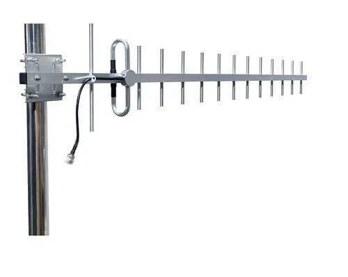 Outdoor Yagi TV Antenna


 Ceiling mount antenna
  Wall mount panel antenna
 Fiberglass Antenna
  Panel Antenna
  Parabolic Antenna
  Yagi Antenna


