


GLFPC075
GLOBAL
8517710000
100PC
Accepted
10000PC/Day
| Quantity: | |
|---|---|
| PDF Export | |


Item | FPC |
PN | GLFPC075 |
Frequency Range (MHz) | 700-2700 |
Gain (dBi) | 3 |
V.S.W.R | ≤1.5 |
Max power input(W) | 20 |
Connector | IPEX or welding |
Dimension | 8.3x35.8mm |
Product Introduction
1.Ultra-Wide Band Compatibility:Covering the 700-2700MHz key frequency band, it is fully compatible with mainstream global 2G, 3G, and 4G LTE networks, as well as multiple IoT frequency bands. A single antenna can meet the deployment needs of multi-mode, multi-frequency devices in different regions worldwide, simplifying design and the supply chain.
2.and Flexible Layout:Utilizing a slim 8.3x35.8mm flexible PCB design, it is ultra-thin and bendable, easily adapting to narrow internal edges or specific curved structures, providing an ideal wireless solution for terminal products seeking ultimate compactness and thinness.
3.High-Performance Signal Transmission:With a Voltage Standing Wave Ratio (VSWR) ≤1.5, it ensures excellent impedance matching between the antenna and the RF front-end, minimizing signal reflection loss and achieving efficient power transmission, thereby guaranteeing stable communication connections and good signal quality.
4.-Interface Flexible Integration:Providing a standard IPEX connector interface (facilitating rapid assembly and testing) and a direct soldering option, it offers highly flexible solutions for different manufacturing processes, cost control, and reliability requirements, facilitating rapid product launch.
5.High Power Tolerance and Reliable Durability: Supports a maximum input power of up to 20W, providing ample power margin for various communication devices and ensuring stable operation under high loads. The flexible material is robust and durable, able to withstand assembly stress and long-term use.
Application Scenarios
●Smart Metering Devices: Integrated into 4G Cat.1/NB-IoT smart water meters, electricity meters, and gas meters for remote meter reading.
●Asset Tracking and Positioning Terminals: Used in vehicle GPS trackers, logistics monitoring tags, and valuable asset locators.
●Industrial Equipment: Provides wireless connectivity for handheld data acquisition devices, industrial PDAs, and mobile payment terminals.
●Smart Security Products: Used in 4G network cameras, wireless alarm hosts, and smart access control systems.
●Compact IoT Modules: Built into IoT communication modules or sensor devices with strict size requirements.
FAQ
Q: Which specific network frequency bands does this antenna support?
A: Its 700-2700MHz coverage range includes many key frequency bands, such as China Mobile's 700MHz (Band 28) and 900MHz (Band 8), China Unicom/China Telecom's 1800MHz (Band 3), and the globally widely used 2100MHz (Band 1). Specific support depends on the frequency band design of the device's RF front-end.
Q: Can it be used in 5G devices?
A: Not fully supported. The highest frequency of GLFPC075 is 2700MHz, while mainstream 5G Sub-6GHz bands (such as n78: 3300-3800MHz) are higher than this range. However, it can be used in 5G devices for 4G fallback (LTE) or low-frequency band connectivity that requires compatibility.
Q: Is there a performance difference between IPEX connection and soldering methods?
A: When correctly implemented, there is no fundamental difference in RF performance between the two. IPEX connections facilitate production line operations and maintenance; direct soldering provides a more permanent and reliable mechanical connection, and is less expensive and requires less space. The choice depends on your production processes and design priorities.
Q: What is the most critical design rule for mounting this antenna on the PCB?
A: The most important thing is to ensure sufficient and proper clearance. Clearance must be made on all PCB layers (especially the ground plane) directly below the antenna radiator, and the area around the antenna must be kept away from metal components and batteries. Incorrect clearance design is a major cause of antenna performance degradation.
Q: Does a 3dBi gain mean a weak signal?
A: Not necessarily. 3dBi is a typical practical gain for this type of small omnidirectional antenna. Communication distance depends on the full system link budget. With reasonable transmit power and receive sensitivity, this gain is sufficient for most IoT and short-to-medium range mobile communication applications.
Q: How to secure the antenna inside the device?
A: We recommend using high-temperature resistant thin double-sided tape (such as EMI shielding tape with conductive backing or 3M 9448 series) to attach it to the inner wall of the equipment housing or non-metallic bracket. Ensure the surface to be pasted is flat and clean.


 External GPS Antenna
  Ceramic antenna
  Internal GPS Antenna
  Surveying Antenna
 Magnet Antenna
  Patch Antenna
  Rubber Antenna
  Screw Antenna
  Spring Antenna
  Other Indoor Coverage Antenna&outdoor Wlan Antenna
 2.4G Antenna
  5.8G Antenna

 Outdoor Yagi TV Antenna


 Ceiling mount antenna
  Wall mount panel antenna
 Fiberglass Antenna
  Panel Antenna
  Parabolic Antenna
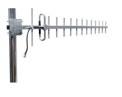
  Yagi Antenna


