
Views: 0 Author: Site Editor Publish Time: 2026-01-28 Origin: Site


GPS antennas are critical components in GNSS systems, enabling accurate positioning for industries like surveying, agriculture, and telematics. This blog breaks down key specs—gain, frequency, and polarization—to help you select the right antenna from reliable Chinese manufacturers.
Antenna gain measures how effectively an antenna directs or concentrates radio signals in a particular direction, expressed in decibels (dB). For GPS antennas, gain typically ranges from 20 dB to 40 dB, amplifying weak satellite signals for better reception.
Higher gain improves low-elevation satellite tracking, which is vital in obstructed environments like urban areas or under foliage. However, excessive gain can increase noise and multipath interference, so balanced designs with excellent low-elevation gain are ideal for high-precision tasks like RTK positioning.
Passive antennas offer lower gain but avoid low-noise amplifier (LNA) issues, while active ones boost signals with 25-40 dB gain for long-range applications.
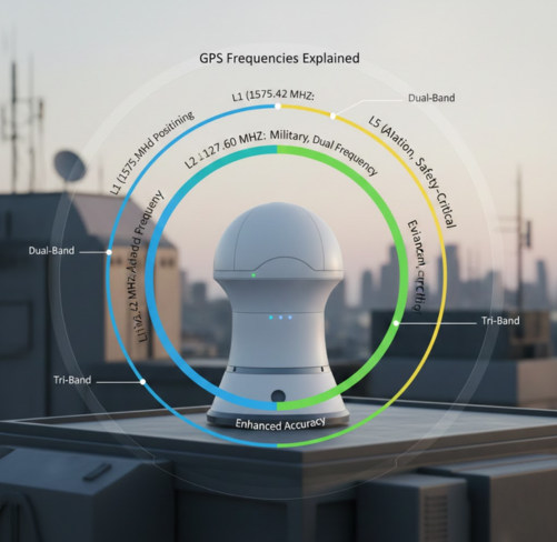
GPS antennas must support specific frequency bands used by GNSS constellations: L1 (1575.42 MHz) for civilian GPS, L2 (1227.60 MHz) for dual-frequency correction, and emerging L5 (1176.45 MHz) for improved accuracy.
Multi-band antennas cover GPS (USA), GLONASS (Russia), BeiDou (China), and Galileo (Europe), ensuring compatibility across global systems. For example, high-precision GNSS antennas handle L1/L2/L5 for RTK and DGPS, delivering stable phase centers in surveying, Anti jamming antennas, and precision agriculture.
Frequency coverage directly impacts receiver sensitivity; broader bands reduce cross-correlation errors and support advanced techniques like multi-constellation positioning.
Polarization describes the orientation of electromagnetic waves. GNSS satellites transmit right-hand circular polarization (RHCP) signals, so matching RHCP antennas are essential to avoid fading from satellite orientation changes.
Circular polarization resists ionospheric Faraday rotation and multipath from reflections, outperforming linear types. Axial ratio (ideally near 0 dB, under 3 dB practical) measures purity—lower values mean better RHCP rejection of left-hand (LHCP) cross-polarization noise.
RHCP antennas excel in dynamic uses like vehicles, maintaining signal integrity regardless of rotation.
Gain patterns define directional sensitivity, ideally hemispherical for skyward satellite coverage with roll-off at horizons to suppress multipath. Perfect patterns are uniform above the horizon, but optimized designs balance this with noise temperature control.
Phase center stability ensures consistent signal arrival points, critical for centimeter-level accuracy in surveying. Ground plane dependence affects patch antennas, so survey-grade models minimize variations.
In tough conditions, high-gain RHCP antennas with low axial ratios provide superior tracking.
Surveying and mapping rely on multi-frequency, high-gain antennas for RTK baselines under 1 cm. Precision agriculture uses vehicle-mounted GNSS antennas for autonomous tractors, tracking low-elevation signals amid fields.
Anti jamming antennas demand lightweight helical or patch designs with broad frequency support for stable flight paths. Automotive telematics benefits from helical antennas amplifying signals in motion.
Digital construction integrates these for machine control, reducing errors in heavy equipment.
Type | Gain Range | Frequency Support | Polarization | Best For | Key Traits |
Patch | 20-30 dB | L1 or Multi-band | RHCP | Fixed installs, survey | Compact, ground-plane dependent, stable phase center |
Helical | 25-40 dB | L1/L2/L5 | RHCP | Vehicles, Anti jamming antennas | High gain, omnidirectional, signal amplification |
Quadrifilar Helix (QFH) | 15-25 dB | L1 primary | RHCP | Handhelds, portable | Wide beamwidth, low profile |
Active w/ LNA | +25-40 dB | Multi-band | RHCP | Long cable runs | Noise figure critical, FCC regulated |
Patch antennas suit static high-precision needs; helicals excel in mobile scenarios.
Match gain to environment: 25-30 dB for open skies, 35+ dB for obstructed views. Prioritize multi-frequency for future-proofing and RHCP with <2 dB axial ratio for purity.
Consider noise figures in active units and multipath rejection via pattern roll-off. Test phase center charts for your application.
China leads GNSS antenna production with cost-effective, high-spec options rivaling global brands. Suppliers offer customizable high-gain, multi-band RHCP models for RTK and DGPS, ideal for B2B exports.
Explore AsiaLeren's GPS/GNSS Antennas
High-precision antennas with superior gain, low-elevation tracking, and circular polarization. Manufactured in China for global supply—perfect for surveying, Anti jamming antennas, agriculture, and construction.
Shop Now – Reliable supplier, competitive pricing, fast shipping.
1. What is GPS Antenna Gain?
Antenna gain measures signal focusing power in dB, typically 20-40 dB for GNSS models. Higher gain (e.g., 35+ dB) boosts weak satellite signals in obstructed areas but risks noise; balance it for your environment.
2. How Does Frequency Affect Performance?
GPS antennas target L1 (1575 MHz), L2 (1227 MHz), and L5 (1176 MHz) bands for GPS/GLONASS/BeiDou/Galileo. Multi-frequency support cuts errors and enables RTK precision under 1 cm.
3. Why RHCP Polarization?
GNSS uses right-hand circular polarization (RHCP) to counter satellite rotation and multipath. Axial ratio under 3 dB ensures signal purity, rejecting LHCP noise.
4. Active vs Passive Antennas?
Active antennas add 25-40 dB gain via LNA for long cables; passive ones suit short runs with lower noise risk. Match to receiver voltage (3-5V).
5. Patch vs Helical Types?
Patch antennas (20-30 dB gain) excel in fixed installs with stable phase centers; helical (25-40 dB) suit mobile uses like vehicles/Anti jamming antennas for omnidirectional RHCP.
6. What Causes Poor Signal?
Obstructions, multipath, high noise figure (>2 dB), or mismatched impedance (50 ohms standard). Ensure sky view and RHCP alignment.
7. Multi-Band vs Single-Band?
Multi-band covers all GNSS for global accuracy; single-band (L1) suffices for basic tracking but limits precision in challenging conditions.
8. Best Installation Tips?
Mount with horizon view, away from metal; use 300 ft max cable for passive. Test phase center stability for surveying.


 External GPS Antenna
  Ceramic antenna
  Internal GPS Antenna
  Surveying Antenna
 Magnet Antenna
  Patch Antenna
  Rubber Antenna
  Screw Antenna
  Spring Antenna
  Other Indoor Coverage Antenna&outdoor Wlan Antenna
 2.4G Antenna
  5.8G Antenna

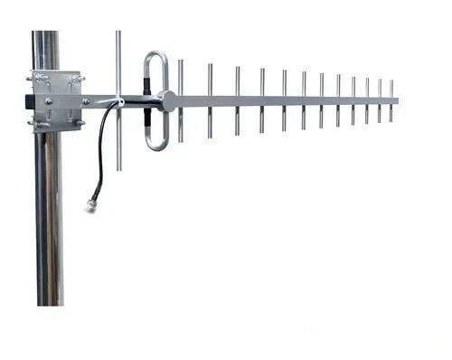 Outdoor Yagi TV Antenna


 Ceiling mount antenna
  Wall mount panel antenna
 Fiberglass Antenna
  Panel Antenna
  Parabolic Antenna
  Yagi Antenna


