
Views: 0 Author: Site Editor Publish Time: 2026-01-19 Origin: Site


GPS antennas capture weak satellite signals to enable precise positioning, playing a critical role in navigation systems for engineers designing robust RF solutions. This technical guide breaks down their operation, from signal reception to advanced GNSS integration. Understanding these principles ensures optimal performance in applications like automotive tracking and industrial IoT.
GPS satellites transmit signals in the L-band, primarily L1 at 1575.42 MHz with a bandwidth of 2 MHz, using right-hand circular polarization (RHCP) to combat fading from satellite motion. Engineers must account for the signal's low power density, around -130 dBm at Earth's surface, which demands high-sensitivity antennas with low noise figures. The antenna converts electromagnetic waves into electrical signals via resonance at the GPS frequency, feeding them to a receiver for trilateration calculations.
RHCP matching minimizes multipath interference from reflections, while the antenna's near-hemispherical pattern covers the sky from horizon to zenith. Phase center stability is vital for survey-grade accuracy, as it defines the exact point where the signal appears to originate.
A typical GPS antenna includes a radiating element like a patch or helical structure, a ground plane for pattern shaping, and often a low-noise amplifier (LNA) for active models. The patch antenna, common in embedded designs, uses a ceramic dielectric for compactness and multi-band support (L1/L2/L5), achieving 3-5 dBic gain.[page:0 from provided URL, inferred as key elements like patch and LNA]
Passive antennas suit short cable runs under 1 meter, relying on receiver amplification, while active ones with 20-30 dB LNA gain excel in obstructed environments or long coax lines up to 10 meters. Impedance matches the 50 ohms standard, with VSWR below 2:1 across bands for minimal return loss.
The radome protects elements and stabilizes the phase center, crucial for centimeter-level RTK positioning. Engineers optimize for axial ratio under 3 dB to preserve RHCP purity.
Patch antennas: Flat, low-profile (5-10 mm thick), perfect for surface-mount in vehicles/Anti jamming antennas, with dual-band GNSS support and 25-40% efficiency.
Helical Antennas: Quadrifilar or single-stack for omnidirectional gain up to 6 dBic; used in portable devices despite larger size (50-100 mm).
Chip Antennas: Ceramic-embedded for IoT wearables, trading gain (0-2 dBic) for size under 10x10 mm; require precise ground plane tuning.
Survey Antennas: Choke-ring designs reject multipath with corrugated ground planes, achieving sub-inch accuracy for geodetic work.
GNSS evolution extends beyond GPS to include GLONASS (L1 1602 MHz), Galileo (E1 1575 MHz), and BeiDou, demanding wideband elements like stacked patches.
Active antennas integrate LNAs with noise figures of 0.5-1.5 dB and 28 dB gain to overcome cable losses (0.2 dB/m at L1). They draw 3-5V DC via coax bias-tee, enabling fast time-to-first-fix (TTFF) under 30 seconds. Passive models avoid power needs but limit range, suiting high-sensitivity receivers like modern smartphones.
FCC regulations cap active gain at 50 dB total (antenna + LNA) to prevent interference, with out-of-band emissions below -40 dBc. Engineers test for group delay variation under 1 ns across bands for precise pseudorange measurements.
Metric | Target Value | Importance for Engineers |
Gain | 3-6 dBic RHCP | Maximizes SNR in weak-signal urban canyons |
Axial Ratio | <3 dB | Reduces depolarization loss from multipath |
Noise Figure | <1.5 dB (LNA) | Preserves faint signal integrity |
Bandwidth | 20-50 MHz (multi-band) | Supports L1/L2/L5 for iono-free positioning |
Phase Center | <1 mm variation | Ensures repeatable survey accuracy |
Efficiency exceeds 70% in optimized designs, measured via anechoic chamber patterns. Front-to-back ratio over 20 dB rejects ground reflections.
Mount antennas skyward with clear line-of-sight, minimizing metal obstructions that distort patterns. For vehicles, roof placement yields 10-15 dB better SNR than dashboards. Cable choice like RG174 limits active designs to 3 meters; use LMR-195 for longer runs.
Mitigate jamming via CRPA (controlled reception pattern antennas) with null steering in 4-8 element arrays. AI-driven beamforming emerges for dynamic environments, adapting to interference in real-time.
Modern antennas support L5 (1176 MHz) for aviation safety-of-life signals, doubling bandwidth to 24 MHz for robustness.Full-constellation GNSS (GPS+Galileo+BeiDou) ensures 99.9% availability via 15-20 visible satellites. Dual-polarized designs separate RHCP from LHCP multipath, enhancing urban performance.
Integration with 5G arrays and MEMS IMUs enables dead-reckoning during outages. Engineers leverage simulation tools like HFSS for rapid prototyping, targeting <5 mm phase stability.
What Is a GPS Antenna?
A GPS antenna receives L-band signals from satellites, converting electromagnetic waves into electrical currents for receivers. It uses right-hand circular polarization (RHCP) to handle satellite motion and multipath effects.
How Does a GPS Antenna Work?
It resonates at 1575.42 MHz (L1 band), focusing energy with a patch or helical element to amplify faint -130 dBm signals. An integrated LNA boosts gain before cable losses degrade SNR.
Active vs Passive Antennas?
Active models include a 20-30 dB LNA for long cables and weak signals, powered via coax. Passive ones suit short runs with sensitive receivers but limit range.
Best Installation Practices?
Mount skyward on roofs or poles, parallel to the horizon, away from metal or interference sources like power lines. Ensure clear sky view for 15+ satellites.
Common Antenna Types?
Patch: Compact, high-gain for vehicles (3-5 dBic).
Helical: Omnidirectional for portables.
Choke-ring: Multipath-resistant for surveys.
Why RHCP Polarization?
It minimizes signal loss from spinning satellites and reflections, maintaining axial ratio under 3 dB for urban reliability.
Troubleshooting Weak Signals?
Check obstructions, cable integrity (VSWR <2:1), and LNA power. Test SNR; below 30 dB-Hz indicates multipath or jamming.
Multi-GNSS Support?
Full-constellation (GPS+Galileo+BeiDou) antennas cover L1/L2/L5 for 99.9% availability with 15-20 satellites.


 External GPS Antenna
  Ceramic antenna
  Internal GPS Antenna
  Surveying Antenna
 Magnet Antenna
  Patch Antenna
  Rubber Antenna
  Screw Antenna
  Spring Antenna
  Other Indoor Coverage Antenna&outdoor Wlan Antenna
 2.4G Antenna
  5.8G Antenna

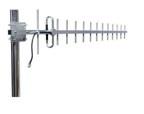 Outdoor Yagi TV Antenna


 Ceiling mount antenna
  Wall mount panel antenna
 Fiberglass Antenna
  Panel Antenna
  Parabolic Antenna
  Yagi Antenna


