

Views: 0 Author: Site Editor Publish Time: 2026-08-06 Origin: Site


Why does a simple antenna design remain widely used in modern wireless systems? As one of the most fundamental antenna structures, the dipole antenna continues to provide reliable performance for various RF and wireless applications. This article explores how dipole antennas work and why they are still an important choice today.
A dipole antenna is one of the simplest and most widely used types of radio antennas. It consists of two identical conductive elements, such as metal rods, tubes, or wires, arranged symmetrically and separated by a small gap. This gap acts as the feed point, where a transmission line connects the antenna to a radio transmitter or receiver.
In a typical half-wave dipole antenna, the two conductive arms are each approximately one-quarter of the operating wavelength (λ/4), creating a total antenna length close to half a wavelength (λ/2). The symmetrical structure allows the two elements to carry equal currents in opposite directions, enabling the antenna to efficiently transmit and receive electromagnetic waves.
The term “dipole” comes from its two conductive poles, which form the two sides of the antenna structure. Unlike more complex antenna designs, a dipole antenna has a simple construction while providing predictable radiation characteristics.

When a dipole antenna operates in transmission mode, an RF signal from the transmitter is applied to the antenna through the center feed point. The alternating voltage at the feed point drives oscillating current along the two conductive elements of the dipole.
In a typical half-wave dipole antenna, the total length is approximately half of the operating wavelength (λ/2). The relationship between wavelength and operating frequency can be calculated using:

where λ is the wavelength, c is the speed of light (approximately 3 × 10⁸ m/s), and f is the operating frequency.
For example, a dipole antenna designed for a 100 MHz VHF signal has a wavelength of approximately 3 meters. Therefore, its total length is about 1.5 meters (λ/2). This length allows the current and voltage to form a stable standing wave distribution, with the current reaching its maximum near the feed point and the voltage reaching its maximum at the ends of the antenna.
The changing current and charge distribution along the dipole arms create the conditions for the formation of alternating electromagnetic fields.
The oscillating current flowing through the dipole elements generates a changing magnetic field (H-field) around the conductors. Because the direction and strength of the RF current continuously vary, the magnetic field also changes with the same frequency as the applied signal.
At the same time, the alternating current causes electrons to move back and forth along the dipole elements, creating a periodic redistribution of electric charges. Since the two ends of a dipole antenna are open circuits, charges accumulate at the ends and produce a changing electric field (E-field).
The alternating electric and magnetic fields are closely coupled and exist together around the dipole element, forming the dynamic electromagnetic field that characterizes dipole antenna operation.
The alternating electric and magnetic fields generated by the dipole antenna initially exist mainly in the region surrounding the antenna, known as the near field. In this area, part of the electromagnetic energy is temporarily stored and continuously exchanged between the electric and magnetic fields.
As the RF signal continues to drive the antenna, the changing electromagnetic fields extend farther away from the conductor. A portion of this energy separates from the antenna structure and becomes a self-propagating electromagnetic wave, which travels through free space at the speed of light.
In the far-field region, the electric and magnetic fields are perpendicular to each other and to the direction of wave propagation. This organized relationship allows the radiated energy to travel over long distances and carry information in wireless communication systems.
When an RF signal is applied to a dipole antenna, the alternating current oscillating along the two conductive elements generates continuously changing electric and magnetic fields. These electromagnetic fields gradually detach from the antenna structure and propagate outward in the form of electromagnetic waves. However, the radiated energy is not distributed uniformly in all directions; instead, it is influenced by the current distribution along the antenna and the interaction of electromagnetic waves generated from different sections of the antenna.
For a half-wave dipole antenna, the current is strongest at the center feed point and gradually decreases toward the two ends. This radiation difference, formed by the current distribution and the spatial interaction of electromagnetic waves, ultimately creates the characteristic three-dimensional doughnut-shaped (toroidal) radiation pattern of a dipole antenna.
In simple terms, the working process of a dipole antenna can be summarized as:
RF current oscillation → Electromagnetic field generation → Electromagnetic wave radiation → Wireless signal transmission.

To make a dipole antenna resonate at your target frequency, the total length of the antenna must equal half a wavelength (λ/2).
In real life, electric signals travel slightly slower through copper wire than through thin air. Because of this, the actual wire length needs to be slightly shorter than the theoretical math. You can calculate the exact physical length using these standard rules:

· Total Length (L): The end-to-end length of the complete antenna.
· Each Arm (L/2): Since a dipole has two equal sides, divide the total length by 2 to get the length of each wire rod.
If you need an antenna for a 100 MHz radio signal:
1. Total length = 142.5 / 100 = 1.425 meters
2. Each wire arm = 1.425 / 2 = 0.7125 meters (or 71.25 cm)
The half-wave dipole is the standard reference structure for most dipole antennas. It consists of two conductors of equal length, with a total length close to half the operating wavelength (approx. λ/2). At this length, the antenna operates in a resonant state with an input impedance of about 73 Ω. Compared to other dipole designs, the half-wave dipole provides a balanced current distribution, high radiation efficiency, and a stable radiation pattern, making it widely used in RF communications, broadcasting systems, and VHF/UHF communication systems.
Compared to the standard half-wave dipole, the folded dipole adds a parallel conductor connected at both ends to form a closed-loop structure. This configuration alters the current path and increases the input impedance to approximately 300 Ω (about 4 times that of a standard half-wave dipole) while maintaining a similar radiation pattern. Excellent high-impedance characteristics make the folded dipole easier to match with traditional 300 Ω twin-lead transmission lines, which is why it is commonly used in television antennas and FM receiving antennas.
The short dipole significantly reduces physical length compared to the standard half-wave dipole (much smaller than λ/2), making it suitable for space-constrained applications. However, shortening the antenna causes it to become capacitive (current leads voltage) and drastically lowers its radiation resistance. This results in reduced radiation efficiency, a narrow bandwidth, and difficult impedance matching. Consequently, short dipoles are primarily used in scenarios where compact size is critical and top-tier performance is not required.
The loaded dipole overcomes the limitations of the short dipole by integrating additional elements, such as loading coils (inductive components) or capacitive elements. Since short dipoles inherently exhibit high capacitive reactance, adding inductive reactance via series coils cancels out the capacitive reactance. This increases the electrical length of the antenna, allowing a physically shorter antenna to resonate at the target frequency. Compared to a standard half-wave dipole, the loaded dipole offers a more compact solution while maintaining acceptable radiation performance.
Unlike standard half-wave dipoles, which typically operate efficiently only over a narrow frequency range, broadband dipoles achieve wider frequency coverage by modifying their structural design. By expanding the cross-sectional area of the conductor—such as in biconical or bow-tie structures—the antenna's quality factor (Q factor) is reduced. A lower Q factor means energy is radiated more quickly, allowing the antenna to maintain stable impedance characteristics over a broad frequency range. This makes it ideal for EMC testing, measurement systems, and spectrum monitoring applications.
Structural Simplicity and Minimal Cost
A basic half-wave dipole requires only two symmetrical conductive rods or wires fed at the center, eliminating the need for complex RF substrates or multi-layer geometries. This minimalist structure minimizes bill-of-materials (BOM) costs and enables effortless high-volume manufacturing.
Deterministic Radiation Patterns
Oriented vertically, the dipole produces an omnidirectional pattern in the azimuth plane (H-plane) for complete 360° coverage. In the elevation plane (E-plane), it forms a symmetric figure-8 pattern with sharp nulls along the element axis, allowing engineers to exploit these blind spots to reject co-channel interference.
Analytical Reference Standard
Because its electromagnetic field distribution has an exact mathematical solution, the half-wave dipole serves as the absolute baseline (0 dBd ≈ 2.15 dBi) for antenna gain calibration. It is the universally recognized reference in EMC compliance labs for evaluating unknown radiators.
Inherent Resonance and Native Impedance Alignment
At resonance, the antenna's reactance drops to zero (becoming purely resistive), eliminating reactive losses and yielding radiation efficiency near 100%. Its free-space input impedance of roughly 73 Ω naturally matches standard 75 Ω coaxial cables. When interfacing with 50 Ω systems, it requires no complex matching networks—simply slanting the elements downward into an Inverted-V configuration directly drops the impedance to 50 Ω for a perfect match.
• FM and TV Broadcasting: Deploys vertical or horizontal dipoles (often configured as folded dipoles) on broadcast towers. Their uniform 360° H-plane coverage ensures wide-area signal distribution across metropolitan zones without demanding directional alignment at the receiver.
• Land Mobile and VHF/UHF Land-Based Radios: Uses stacked dipole arrays in emergency dispatch and maritime base stations. Their symmetric vertical radiation pattern leverages ground reflections to maximize line-of-sight range while maintaining structural durability against harsh weather.
• Ground-Independent IoT Gateways and Wireless Nodes: Employs external "rubber duck" dipoles on Wi-Fi routers and industrial smart gateways. As balanced radiators, dipoles operate independently of the host PCB ground plane, avoiding the detuning caused by compact internal electronics.
• Cellular Infrastructure and Base Station Arrays: Integrates orthogonal pairs—known as cross-polarized dipoles (±45°)—as fundamental radiator elements in 4G/5G macro cells. Arranged in vertical arrays, they deliver high polarization isolation, mitigate multipath fading, and enable precise dynamic beamforming.
• EMC Compliance and RF Metrology Standards: Serves as the gold-standard reference antenna in Anechoic and Open Area Test Sites (OATS). Because their far-field electromagnetic flux is analytically solvable, half-wave dipoles are universally mandated by regulatory bodies (e.g., CISPR, FCC) to calibrate unknown radiators and measure Effective Radiated Power (ERP).
Feature | Dipole Antenna | Monopole Antenna |
Structure | Two conductive elements with equal length | Single conductive element using a ground plane as the return path |
Electrical Length | Usually λ/2 | Usually λ/4 |
Ground Plane Requirement | Does not require a ground plane | Requires a conductive ground plane or counterpoise |
Radiation Pattern | Omnidirectional in H-plane with symmetric figure-8 pattern in E-plane | Similar omnidirectional coverage but only above the ground plane |
Gain Reference | 0 dBd (≈2.15 dBi) | About 5.15 dBi over an ideal ground plane |
Impedance | Around 73 Ω at resonance | Around 36.5 Ω at resonance |
Installation | More independent, suitable for balanced systems | More compact, common in mobile devices and vehicles |
Yes, a 1:1 current balun is strongly recommended. A dipole is a balanced antenna, while coaxial cable is an unbalanced feedline. Direct connection causes RF current to flow back along the outer shield of the coax, leading to feedline radiation, higher local noise, and erratic SWR readings.
To maintain its nominal 73 Ω impedance and desired radiation pattern, mount the dipole at least half a wavelength (λ/2) above the ground. Mounting it below λ/4 causes heavy ground coupling, which drops input impedance, increases soil losses, and forces the radiation angle upward.
Formulas calculate ideal length in free space. Surrounding structures, trees, soil conductivity, and height all shift the resonant frequency. Measure with an antenna analyzer:
· If minimum SWR occurs below your target frequency, the antenna is too long (trim it).
· If minimum SWR occurs above your target frequency, the antenna is too short (extend it).


 External GPS Antenna
  Ceramic antenna
  Internal GPS Antenna
  Surveying Antenna
 Magnet Antenna
  Patch Antenna
  Rubber Antenna
  Screw Antenna
  Spring Antenna
  Other Indoor Coverage Antenna&outdoor Wlan Antenna
 2.4G Antenna
  5.8G Antenna

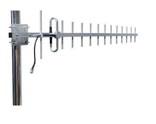 Outdoor Yagi TV Antenna


 Ceiling mount antenna
  Wall mount panel antenna
 Fiberglass Antenna
  Panel Antenna
  Parabolic Antenna
  Yagi Antenna


