

Views: 0 Author: Site Editor Publish Time: 2026-08-07 Origin: Site


At first glance, SMA and RP-SMA connectors look almost identical. They have the same size, the same threads, and they can even screw together perfectly. But here’s the catch, they are not the same connector.
It’s like trying to use the wrong key for a lock. The key may look almost identical and fit into the keyhole, but the internal shape is slightly different, so it still cannot unlock the door. SMA and RP-SMA connectors work in a similar way, the difference is hidden inside the connector.
So, how can you quickly tell SMA and RP-SMA connectors apart? In this guide, we’ll compare their key differences and show you the easiest way to identify the right connector for your application.
SMA and RP-SMA have no significant difference in RF performance. Both are designed for 50Ω RF systems. The main difference is the connector structure and the standards adopted by different devices.
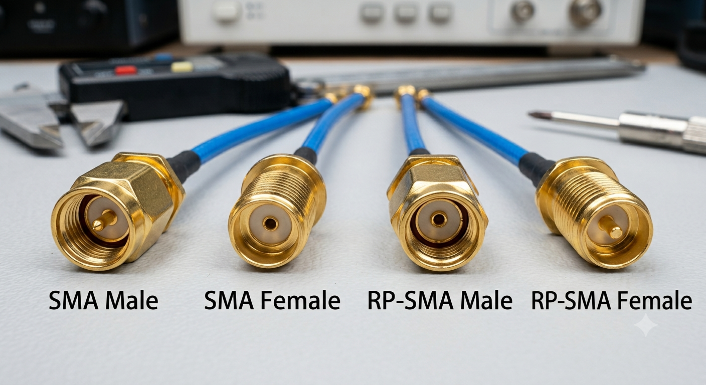
Thread Structure | Center Contact | Connector Type |
External Thread | Pin | SMA Male |
Internal Thread | Socket | SMA Female |
External Thread | Socket | RP-SMA Male |
Internal Thread | Pin | RP-SMA Female |
Male and female connectors are identified by their thread structure: external threads indicate a male connector, while internal threads indicate a female connector. SMA and RP-SMA connectors are distinguished by their center contact arrangement: a standard pin/socket arrangement indicates SMA, while the reversed pin/socket arrangement indicates RP-SMA.
Choosing the right antenna is not only about selecting SMA or RP-SMA. The connector type and gender of the antenna must match your device.
Before purchasing an antenna, check the connector on your device first. If your device uses an SMA connector, choose an SMA antenna. If it uses an RP-SMA connector, choose an RP-SMA antenna.
At the same time, make sure the connector gender matches. Male connectors connect to female connectors, and female connectors connect to male connectors.
For example:
· SMA Female device → SMA Male antenna
· RP-SMA Female device → RP-SMA Male antenna
Asialeren provides a wide range of antennas with SMA and RP-SMA connectors, making it easier to find the right antenna for your specific device and application.
A connector that can be screwed on smoothly only means that the physical connection is successful, but it does not mean that the RF signal can be transmitted properly. If the connector is fully matched but the device still has no signal, the problem usually comes from the following 3 key factors:
· Frequency Mismatch: The antenna connector is universal, but the internal structure of the antenna is designed for specific frequency ranges. If a 2.4GHz Wi-Fi antenna is connected to a 4G/5G module or GPS interface, the connector may fit perfectly, but the antenna cannot receive or transmit signals in that frequency band.
· Impedance Mismatch: Most wireless devices and antennas use a standard impedance of 50 ohms (Ω). If a 75-ohm antenna commonly used for broadcasting or cable TV is incorrectly selected, it can cause serious signal reflection (high VSWR), resulting in poor signal performance and potentially damaging the RF front end of the device.
· Installation Limitations:If the connector is located inside a narrow enclosure or installed close to a wall, a straight antenna may be restricted from bending properly, causing internal cable damage or poor contact. In such cases, a 90-degree angled connector or an extension cable may be needed to ensure a secure installation without mechanical stress.
Complete Signal Disruption Due to SMA and RP-SMA Confusion
Mixing up SMA and RP-SMA causes total connection failure despite compatible outer threads. Connecting an SMA Male to an RP-SMA Female leaves a "socket-to-socket" gap, while connecting an RP-SMA Male to an SMA Female causes a "pin-to-pin" collision. Both scenarios result in 100% signal loss.
Signal Attenuation and Dropouts from Poor Contact
Off-spec SMA or RP-SMA adapters prevent proper pin engagement. This loose contact creates an extremely high Voltage Standing Wave Ratio (VSWR), reflecting RF energy back instead of radiating it, causing severe signal loss and frequent disconnects.
Overheating of High-Power Transmitter Modules
Choosing the wrong SMA or RP-SMA connector on high-power devices (like FPV transmitters or 4G/5G gateways) leaves the transmitter operating without a load. Reflected RF power accumulates in the Power Amplifier (PA), risking rapid overheating and permanent hardware burnout.
A high-quality adapter introduces minimal signal loss (usually less than 0.1–0.3 dB), which is negligible for most applications. However, ensure the adapter is tight and fully seated to prevent high VSWR and intermittent disconnects.
Standard SMA and RP-SMA connectors are not waterproof on their own. Water can enter through the thread gaps and destroy coax cables via capillary action. For outdoor installations (such as Helium miners, LTE/5G outdoor CPEs, or weather stations), you must either use IP67-rated weather-sealed connectors or wrap the joint tightly with self-amalgamating silicone tape.
Gold-plated brass provides excellent conductivity and corrosion resistance for indoor use, but soft brass wears down quickly after ~500 mating cycles. Stainless steel connectors are far more durable and required for harsh outdoor or marine environments. Nickel-plated bodies are cost-effective but offer slightly higher RF loss at ultra-high frequencies.


 External GPS Antenna
  Ceramic antenna
  Internal GPS Antenna
  Surveying Antenna
 Magnet Antenna
  Patch Antenna
  Rubber Antenna
  Screw Antenna
  Spring Antenna
  Other Indoor Coverage Antenna&outdoor Wlan Antenna
 2.4G Antenna
  5.8G Antenna

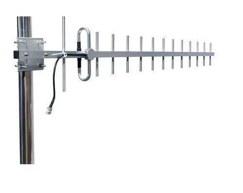 Outdoor Yagi TV Antenna


 Ceiling mount antenna
  Wall mount panel antenna
 Fiberglass Antenna
  Panel Antenna
  Parabolic Antenna
  Yagi Antenna


