

Views: 0 Author: Site Editor Publish Time: 2026-08-01 Origin: Site


As IoT applications continue to evolve, choosing the right cellular technology is only part of the design process. LTE and 5G have different requirements for antenna performance, frequency support, and RF design. Selecting the right antenna early can help ensure reliable connectivity, optimize device performance, and avoid costly redesigns.
Many engineering teams still treat cellular connectivity linearly: select a cellular module first, and deal with the antenna during final hardware integration. However, as cellular technologies advance, this traditional approach creates unexpected RF bottlenecks and leads to high-risk hardware redesigns.
Hardware teams must evaluate connectivity and antenna strategy together from the outset due to three key engineering challenges:
Global LTE Band Complexity vs. Space Constraints: LTE remains vital for mid-speed IoT through mature standards like LTE Cat 1 and Cat 1 bis. However, global deployments require supporting specific low-frequency bands (such as LTE Band 28 or Band 71). These lower frequencies require a larger PCB ground plane to achieve proper resonance—creating a major design hurdle for compact devices.
5G RedCap Expands IoT but Keeps RF Challenges: 3GPP Rel-17 5G RedCap offers a practical bridge for lightweight industrial devices and asset tracking. Yet, while RedCap simplifies module architecture compared to full 5G, it does not eliminate RF complexity. Reliable performance across regional Sub-6GHz bands still requires precise antenna tuning and optimization.
The "Module Upgrade, Antenna Redesign" Trap: Transitioning from LTE to 5G is rarely a simple drop-in module replacement. 5G’s wider bandwidths and MIMO multi-antenna requirements place far stricter demands on physical layout. Ignoring antenna placement, ground plane dimensions, and element isolation early on often results in signal detuning, severe interference, and carrier certification failures
Rethinking your connectivity strategy is not just about choosing LTE or 5G. It is about understanding how network selection directly impacts antenna architecture, enclosure materials, and overall RF system performance.
LTE (Long-Term Evolution) is a 4G cellular communication technology widely used for wireless connectivity in IoT devices. By employing OFDM modulation and MIMO multi-antenna technologies, LTE achieves higher data transfer rates, greater network capacity, and more stable connections compared to 3G networks.
While 3G networks typically offer peak speeds of only around 2 Mbps to 42 Mbps with latencies near 100 milliseconds, LTE reaches a theoretical peak download speed of up to 1 Gbps with latency reduced to 30–50 milliseconds, providing real-world commercial data speeds ranging from tens to hundreds of Mbps. LTE remains a vital connectivity solution for IoT applications such as industrial monitoring, asset tracking, smart retail, and various connected devices.
5G (5th Generation Mobile Communication Technology) is a new-generation cellular communication technology that provides higher data transmission speeds, lower latency, and greater device connectivity compared with 4G LTE. By adopting technologies such as Massive MIMO, beamforming, and millimeter-wave communication, 5G improves network capacity and transmission efficiency.
5G can achieve a theoretical peak speed of up to 20 Gbps, while commercial networks typically deliver 100 Mbps to several Gbps. Compared with LTE, 5G supports higher-bandwidth applications such as 4K/8K video, real-time monitoring, and industrial automation, making it suitable for high-performance IoT applications.
Having understood what LTE and 5G are, we can compare their fundamental differences across several key technical dimensions:
• LTE: Reaches a theoretical peak download speed of around 1 Gbps (with LTE-Advanced), while real-world commercial network speeds typically range between 20 Mbps and 100 Mbps.
• 5G: Delivers theoretical peak download speeds of 10 to 20 Gbps, with real-world user speeds often reaching several hundred Mbps to over 1 Gbps—a 10x to 20x speed increase over LTE.
• LTE: Features an average latency of 30 ms to 50 ms.
• 5G: Drastically reduces latency to 1 ms to 10 ms (near zero latency).
• LTE: Supports approximately 100,000 devices per square kilometer.
•5G: Supports up to 1,000,000 devices per square kilometer (a 10x capacity expansion)
• LTE: Operates primarily on Sub-3 GHz low-to-mid frequency bands.
•5G: Utilizes a full-spectrum approach, combining Sub-6 GHz coverage with high-frequency millimeter-wave (mmWave) bands (24 GHz and above).
• LTE: Employs standard MIMO technology (typically 2x2 or 4x4 antenna configurations) that broadcasts wireless signals across broad sectors.
• 5G: Upgrades to Massive MIMO (utilizing dozens to hundreds of antenna elements) paired with Beamforming, allowing the base station to direct targeted signal beams straight to individual devices, significantly reducing interference and boosting efficiency.
• LTE: Built upon the Evolved Packet Core (EPC) architecture, offering relatively rigid and uniform resource allocation.
• 5G: Uses a cloud-native Service-Based Architecture (SBA) that enables Network Slicing. Operators can partition a single physical network into multiple isolated virtual slices tailored specifically for extreme speed, ultra-low latency, or massive IoT connection
needs.

Choosing between LTE and 5G is not a one-size-fits-all hardware decision. Industry requirements dictate not only the cellular technology (throughput, latency, coverage) but also the physical antenna constraints (space, enclosure material, environment).
To avoid costly redesigns, engineering teams must evaluate both connectivity and antenna requirements across key industry scenarios:
Application Scenarios: Smart water/gas meters, underground pipeline monitors, and street lighting.
Network Selection: LTE (NB-IoT / LTE-M) remains the dominant choice. These applications transmit small data packets infrequently and demand battery operation for 10–15 years.
RF Challenge: Devices are often buried underground, inside concrete pits, or enclosed in heavy metal casings, severely attenuating RF signals.
Antenna Solution: High-efficiency embedded FPC or custom internal PCB antennas tuned specifically for sub-GHz low frequencies (e.g., LTE B28/B71). Engineers must ensure sufficient PCB ground plane length early in the mechanical design to maintain range without draining the battery.
Application Scenarios: Global container trackers, cold-chain monitoring, and fleet management.
Network Selection: LTE Cat 1 / Cat 1 bis or LTE-M for cost-effective global roaming. For specialized ultra-high-value assets requiring live multi-camera video, 5G NR is selected.
RF Challenge: Asset trackers are extremely space-constrained and frequently attached directly to large metal surfaces or placed inside shipping containers, causing antenna detuning.
Antenna Solution: Flexible FPC antennas with active tuning or specialized anti-metal patch antennas. The structural design must account for a clearance zone around the antenna to prevent signal loss caused by nearby cargo or metallic bodies.
Application Scenarios: Automated Guided Vehicles (AGVs), automated optical inspection (AOI), and industrial robotics.
Network Selection: 5G NR for ultra-low latency (<1 ms) and high throughput, or 5G RedCap for mid-speed robotics requiring modern 5G network integration at lower hardware costs.
RF Challenge: Industrial environments feature harsh electromagnetic interference (EMI). Furthermore, 5G requires multi-antenna (MIMO) configurations (2x2 or 4x4), making signal isolation inside compact industrial chassis difficult.
Antenna Solution: Ruggedized external multi-in-one combination antennas (cabled pucks/domes) mounted on the exterior of metal enclosures. This isolates the RF system from internal electrical noise and ensures proper physical spacing between MIMO elements to prevent self-interference.
Application Scenarios: Connected ambulances, remote patient monitoring, and critical surgical telemetry.
Network Selection: 5G NR (URLLC) is mandatory when real-time HD video and zero-latency control are required.
RF Challenge: Medical wearables and portable devices operate near the human body (which absorbs RF energy) and must pass strict regulatory certification (SAR/OTA).
Antenna Solution: Custom-designed LDS (Laser Direct Structuring) or specialized internal ceramic patch antennas. Antenna placement must be isolated from internal batteries and optimized for body-worn dielectric conditions to pass carrier compliance tests without sacrificing link stability.
Factor | What to Check | Engineering Action / Rule of Thumb |
1. Enclosure & Form Factor | Metal enclosure vs. compact plastic device | Metal Enclosure: Use external antennas (puck/dipole) or design a plastic “RF window”.Compact Plastic Device: Use internal FPC or LDS antennas with a dedicated PCB clearance zone. |
2. PCB Ground Plane Space | Available continuous ground layer length | Low-Band LTE (B28/B71): Requires ≥ 80–100 mm PCB ground length.If PCB is < 50 mm: Use off-board FPC antennas or active RF tuning to prevent signal loss. |
3. Enclosure Material & Proximity | Plastic type, body-worn, or metal mount | Plastics detune frequency: Always tune and test antennas inside the final enclosure.Near Body / Metal: Choose specialized anti-metal or ground-independent antennas. |
4. Carrier Certification (OTA) | Carrier requirements (e.g., AT&T, PTCRB) | Add a π-matching circuit on your PCB layout early.Perform early 3D EM simulation and TRP/TIS chamber testing to prevent costly launch delays. |
No. While 5G RedCap simplifies device architecture compared to full 5G, it operates across wider Sub-6GHz frequency ranges and requires specific antenna tuning. Simply swapping the module without evaluating the PCB ground plane, element isolation, and enclosure dielectric effects will lead to signal detuning, reduced throughput, and potential carrier certification failures.
LTE Cat 1 bis uses a single antenna (1Rx/1Tx) operating on legacy LTE bands, making it ideal for extremely space-constrained devices. In contrast, 5G RedCap typically requires 1Tx/2Rx (or 1Tx/1Rx in some lightweight profiles) and needs to support broader 5G Sub-6GHz bandwidths. This requires careful multi-antenna isolation and impedance matching.
Plastic and polymer materials possess a specific dielectric constant that pulls the antenna’s resonance frequency lower (known as signal detuning). Testing an antenna on an open, bare PCB does not reflect real-world performance. You must always perform passive matching network tuning inside the final, fully assembled enclosure.


 External GPS Antenna
  Ceramic antenna
  Internal GPS Antenna
  Surveying Antenna
 Magnet Antenna
  Patch Antenna
  Rubber Antenna
  Screw Antenna
  Spring Antenna
  Other Indoor Coverage Antenna&outdoor Wlan Antenna
 2.4G Antenna
  5.8G Antenna

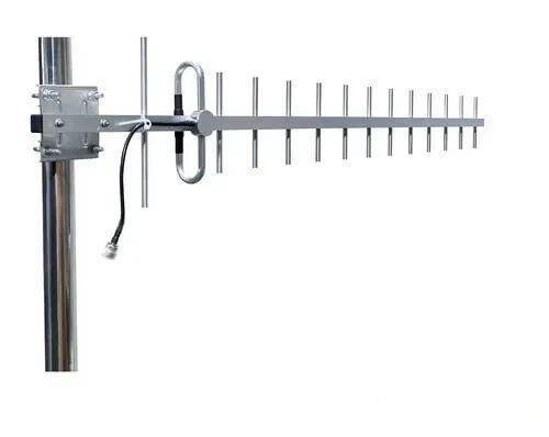 Outdoor Yagi TV Antenna


 Ceiling mount antenna
  Wall mount panel antenna
 Fiberglass Antenna
  Panel Antenna
  Parabolic Antenna
  Yagi Antenna


