

Views: 0 Author: Site Editor Publish Time: 2026-07-29 Origin: Site


After installing a CB antenna, you may expect the radio to work properly right away. However, during actual use, you may notice problems such as audio cutting in and out, increased background noise, unclear conversations, or difficulty transmitting your signal to other users. You may also find that some channels perform better than others.
The problem may not be the antenna quality or the radio itself. In many cases, the antenna simply needs to be properly tuned. Learning how to tune a CB antenna helps ensure that the antenna works efficiently with your CB system, improves transmission performance, and allows you to get the best possible results from your setup.
A CB antenna needs to be tuned to achieve a proper match between the antenna and the radio system. Better matching improves signal transmission efficiency because more RF energy from the CB radio is delivered to the antenna and radiated into the air, while less energy is lost through reflection.
Without proper tuning, a CB antenna may:
· Fail to operate at its optimal performance;
· Reduce transmission efficiency;
· Waste RF power through reflected energy;
· Limit communication range;
· Cause weaker and less reliable signals;
· Put additional stress on the radio system.


In CB antenna tuning, the goal is not to achieve a stronger radio output, but to reduce reflected power by improving the match between the antenna and the radio system. This allows the antenna to use the available RF power more efficiently.
Before tuning your CB antenna, make sure the antenna system is properly installed and ready for testing. A correct setup helps ensure that SWR measurements reflect the actual antenna performance rather than installation problems.
· Gently shake the antenna mount and make sure it does not move or feel loose. Tighten the mounting nuts properly if needed, but avoid excessive force that could damage the threads or mounting parts.
· Make sure the mounting surface is clean and free of paint, rust, or dirt, allowing the antenna mount to maintain direct metal-to-metal contact with the vehicle body.
· Look at the antenna from the side and make sure it is standing as straight as possible without obvious leaning.
· Check that the coaxial connectors are secure. Make sure the connectors at both ends of the coaxial cable are fully tightened. Gently check them by hand to confirm they do not feel loose.
· Inspect the coaxial cable installation. Check the entire cable for cuts, cracks, crushing, sharp bends, or areas where it may be pinched by vehicle parts. Make sure the cable is not pulled too tightly or damaged during installation.
· Confirm the cable connections. Make sure the coaxial cable is connected correctly between the CB radio and the antenna.
· Make sure the antenna has enough surrounding space. Check that the antenna is not blocked by large metal objects, vehicle parts, or other equipment. During testing, park the vehicle in an open area and avoid nearby buildings, fences, other vehicles, or large metal structures that may affect SWR readings.
· Keep the vehicle setup consistent during testing. Make sure doors, trunks, and other vehicle parts remain in the same position during each measurement to avoid changes in SWR readings.
· Check the CB radio power supply. Make sure the radio receives stable power and the voltage is within the normal operating range. Check that the power connections are secure.
· Test the radio operation. Confirm that the radio can transmit and receive normally. If possible, test it with another known working antenna to help determine whether the issue comes from the radio or antenna system.
· Check the radio settings. Make sure the channel, mode, and other settings are correctly configured before tuning the antenna.
SWR (Standing Wave Ratio) shows how efficiently your CB antenna can use the power from your radio.
When the antenna is adjusted correctly, most of the radio’s power can flow into the antenna and be transmitted as radio waves. If the antenna is not adjusted properly, some power is reflected back instead of being transmitted. A lower SWR means less power is reflected and more power is used for communication.
For example, if a CB radio outputs 4 watts of power:
· SWR 1.0:1 means almost all power is transferred to the antenna, with minimal reflection.
· SWR 1.5:1 means the system is well matched, and only a small amount of power is reflected.
· SWR 2.0:1 indicates a noticeable mismatch, with more energy being reflected.
· SWR 3.0:1 or higher suggests a poor match that requires adjustment.
An SWR meter is a tool used to check how efficiently a CB radio can transfer power to the antenna. It measures the SWR value and helps determine whether the antenna needs adjustment during the tuning process.
CB radios may measure SWR through a built-in SWR meter or an external SWR meter. If your radio has a built-in SWR function, you can use it directly. If not, you will need an external SWR meter connected between the radio and antenna to measure SWR during tuning.
1.Choose an open location: Park your vehicle in an open outdoor area, far away from power lines, tall buildings, and large trees.
2.Set the vehicle to its normal state: Close all doors, windows, the hood, and the trunk. Anyone outside should stand at least 2 meters (6 feet) away from the antenna to prevent body capacitance from interfering with the electromagnetic field.
3.Connect the equipment properly: Use a short coaxial jumper cable to connect the antenna port on the back of your CB radio to the TRANS (or XMT) port on the SWR meter. Then connect your antenna's coaxial cable to the ANT port on the SWR meter.
4.Switch to Channel 1: Set your CB radio to Channel 1 (the lowest frequency end).
5.Calibrate for Channel 1: Flip the switch on the SWR meter to CAL (or FWD). Press and hold the PTT (Push-To-Talk) button on your microphone, then turn the CAL knob clockwise until the needle aligns with the CAL / SET mark on the far right of the scale.
6.Measure SWR on Channel 1: While holding the PTT button, switch the meter to SWR (or REF). Read and record the SWR value, then release the PTT button.
7.Switch to Channel 40: Change your CB radio to Channel 40 (the highest frequency end).
8.Measure SWR on Channel 40: Flip the switch back to CAL, press and hold the PTT button, and turn the knob to re-calibrate the needle to the CAL mark. While still holding PTT, flip the switch to SWR, record the reading for Channel 40, and release the PTT button.
Determine length adjustment:
If Channel 40 is higher than Channel 1: The antenna is too long. Loosen the set screw and push the antenna down (shorten it) by 3–6 mm (1/8–1/4 inch).
If Channel 1 is higher than Channel 40: The antenna is too short. Loosen the set screw and pull the antenna up (lengthen it) by 3–6 mm (1/8–1/4 inch).
If both readings are nearly equal and below 1.5: The antenna is properly tuned—skip directly to Step 11.
Repeat testing and fine-tuning: Every time you adjust the physical length, you must repeat Steps 4 through 8 to re-calibrate and measure both Channel 1 and Channel 40 until the SWR readings on both ends drop below 1.5 and are balanced.
Lock in the antenna: Once you are satisfied with the readings, securely tighten all set screws at the base of the antenna to finish tuning.
CB antennas rely heavily on the vehicle's metal body as a ground plane. If the grounding is poor, SWR will remain extremely high. First, check the metal-to-metal contact between the mount and the vehicle body.
For hole-mount or clamp-mount setups, ensure the mounting screws penetrate the paint to make direct contact with bare metal on the vehicle body; if necessary, use sandpaper to lightly scrape away paint inside the mounting hole. For magnetic mounts, ensure the mounting area underneath has a large metal roof surface, and avoid placing it on glass, plastic trim, fiberglass, or aluminum/carbon fiber parts.

Next, check the insulator washer position. On many antenna mounts, such as 3/8"-24 threaded mounts, there is a plastic or nylon insulator washer. A critical detail to remember is that this washer must be installed on the antenna side (top) to isolate the antenna's "positive" center pin from the mount's "ground negative" vehicle body. If it is installed upside down or missing entirely, the antenna will short-circuit directly, causing the SWR reading to spike completely.


 External GPS Antenna
  Ceramic antenna
  Internal GPS Antenna
  Surveying Antenna
 Magnet Antenna
  Patch Antenna
  Rubber Antenna
  Screw Antenna
  Spring Antenna
  Other Indoor Coverage Antenna&outdoor Wlan Antenna
 2.4G Antenna
  5.8G Antenna

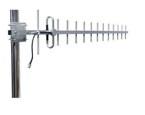 Outdoor Yagi TV Antenna


 Ceiling mount antenna
  Wall mount panel antenna
 Fiberglass Antenna
  Panel Antenna
  Parabolic Antenna
  Yagi Antenna


